15 April 2016

3 DOF Robotic Arm and Car Movement Control Using LabVIEW and NI-myRIO device (Prototype Model)

In this post I have displayed a 3 DOF robotic Arm with Car which can perform Move , pick and place objects .

If you follow my previous post i had built a RC Car controlled by TV Remote http://lookforlk.blogspot.in/2016/03/remote-controlled-car-using-arduino-uno.html

But we do not require all items just Chassis, Wheels , DC Motor(500 RPM) , L293D .

In order to control the arm and car movement I have used Labview 2015 software and myRIO kit .

Robotic Arm has 3 servo motor .Here we have used MG996R  model .

Hardware Used


  • NI-myRIO
  • 3 DOF Robotic Arm (Servos)
  • Chassis with DC Motor and Wheels (Set).
  • L293D IC or L293D Module

Software used

  • LabVIEW 2015


I hope everyone knows basic of Servo motor . Servos have 3 terminals . Vcc , Gnd and they have Pulse Width Modulation (PWM) pin to control the rotation .

L293D Module :

Basically this it used to reverse the polarity 


NI-myRIO :

NI-myRIO is used to generate and acquires signals for controlling and processing, it has an inbuilt processor and FPGA and has many re-configurable analog and digital pins.

NI myRIO

3 DOF Model

This is the 3 Degree of Freedom Model
3 DOF robotic arm model


Control of Car movement


Control of Single arm (Servo) movement


Control of 3 DOF Robotic Arm (Prototype)


My Buddies who helped me build this prototype : Bathirinath , Aravind , Kailash and Karthick

Thank you for Support .

Bookmark & Share if possible :-)

More Post coming on the way ! Stay Tuned !

27 March 2016

Remote Controlled Car using Arduino Uno

Hey Buddies , Wanna control a car with just TV remote ? Here's what you need to learn

You would need IR library , only then you may successfully build it

Get IR library from here and put it on Libraries folder of Arduino in C drive(location where you have installed)


Fully constructed

Thing you need


Motor Shield

Arduino Uno


Components Required :-

1.Chassis
2.Wheels (one castor + two normal wheels)
3.Arduino uno
4,H bridge (L293D Motor Driver IC)
5. DC motors 500 RPM (2 pcs)
6.Breadboard
7.TSOP1738 IC
8. 9V battery (2 pcs)
9. Jumpers
10. TV remote 

Before directly connecting first we have to find the values of  TV remote , Follow the given connections.

Test Connection(for TSOP1738 and Arduino)

1.Arduino Vcc to pin 2
2.Arduino Gnd to pin 1
3.Arduino pin 6 to pin 3

After connecting in the mentioned way upload this code


Code :-

// lookforlk.blogspot.com
#include <IRremote.h>
int RECV_PIN = 6;//pin 6 of arduino to data pin of ir receiver
IRrecv irrecv(RECV_PIN);
decode_results results;

void setup()
{
  Serial.begin(9600);
  irrecv.enableIRIn(); // Start the receiver
}

void loop()
{
  if (irrecv.decode(&results))
    {
     Serial.println(results.value);
     irrecv.resume(); // Receive the next value
          delay(1000);

    }
}


Open the Serial Monitor and then try pressing different buttons ,  the value of the button pressed will be displayed on the Serial Monitor .

Designate 5 buttons
1.Forward
2.Reverse
3.Left
4.Right
5.Stop/Brake

Note down the values it will be used later


Full Connections:-


1.Arduino pin 6 to TSOP1738 IC
2.Arduino pin 8 to Motor Shield pin 2
3.Arduino pin 9 to Motor Shield pin 7
4.Arduino pin 10 to Motor Shield pin 10
5.Arduino pin 11 to Motor Shield pin 15
6.Arduino VCC to Motor Shield VCC
7.Arduino GND to Motor Shield GND
8.TSOP1738 pin 1 to Arduino VCC
9.TSOP1738 pin 2 to Arduino GND

Since you cannot connect more than one pin in Arduino Vcc and Gnd , connect the terminals in common and proceed

Code :-

#include <IRremote.h>
int lm=9;
int lmr=8;
int rm=10;
int rmr=11;

int RECV_PIN = 6;
IRrecv irrecv(RECV_PIN);
decode_results results;

void setup()
{
  pinMode(lm,OUTPUT);
  pinMode(lmr,OUTPUT);
  pinMode(rm,OUTPUT);
  pinMode(rmr,OUTPUT);
  Serial.begin(9600);
  irrecv.enableIRIn(); // Start the receiver
}

void loop()
{
  if (irrecv.decode(&results))
    {
     Serial.println(results.value);
     irrecv.resume(); // Receive the next value
    }
   //bot moves front
    if(results.value==1515192842)
    {
      digitalWrite(lm,LOW);
      digitalWrite(lmr,HIGH);
      digitalWrite(rm,HIGH);
      digitalWrite(rmr,LOW);
    }
    //bot moves back
    if(results.value==1519387146)
    {
      digitalWrite(lm,HIGH);
      digitalWrite(lmr,LOW);
      digitalWrite(rm,LOW);
      digitalWrite(rmr,HIGH);
    }
    //bot moves left
     if(results.value==1485832714)
    {
      digitalWrite(lm,LOW);
      digitalWrite(lmr,HIGH);
      digitalWrite(rm,HIGH);
      digitalWrite(rmr,HIGH);
    }
    //bot moves right
     if(results.value==1485832714)
    {
      digitalWrite(lm,HIGH);
      digitalWrite(lmr,HIGH);
      digitalWrite(rm,HIGH);
      digitalWrite(rmr,LOW);
    }
    //bot stops
    if(results.value==1217397258)
  {
      digitalWrite(lm,HIGH);
      digitalWrite(lmr,HIGH);
      digitalWrite(rm,HIGH);
      digitalWrite(rmr,HIGH);
    }
}
 
Note :-

Change the values in the if condition  


Construct the Body :-

Place the Motor and wheels in Chassis . Connect the terminals of DC motor to Motor shield (in any way , later it can be modified)

Power supply :-


1.Connect a 9v battery to Arduino .
2.Connect 9v battery to Motor shield.


Place everything on chassis and ready to go


For Queries :-
lkkarthikeya@gmail.com


04 March 2016

Laser Trip wire Alarm using Arduino Uno

                              Hey guys ,One more project on Arduino Uno , Laser trip wire Alarm . A laser light is used as wire, when someone tries to cross the laser line the alarm will blow out and alert everyone . This project has vast application but the one application that i loved very much is military where this laser system is installed in Border areas , If there is any trespassing bomb will explode and destroy the extremists . This project may be installed in Indian border areas where it covers vast area of 15,106.7 km of land border and a coastline of 7,516.6 km. OK now lets do it  ...


Components Required :-


1. Arduino UNO
2. Photoresistor
3. Resistor (5 kilo ohm or 10 kilo ohm)
4. Wires
5. Arduino IDE software.
6. Buzzer / LED
7. Laser light


Connection :-


These three terminals can be seen on Left side(Analog) of Arduino UNO

Also connect LED/ Buzzer to 13 and gnd


Here i have used a resistor(1 kilo ohm) after the photodiode . I don't want 5v supply to damage the analog pins since the laser light which when falls on the Photo resistor reduces it resistance and the light will fall on the photodiode for sometime in Real Time (Just a precaution to safeguard my kit).


Coding :-


First of all we must find the Threshold value. i.e The value of photoresistor when the laser light displayed on it and the value when laser light is not displayed on photoresistor .


In order to find threshold value the Test program is simulated first and my code is here :

// test program
//lookforlk.blogspot.in
// we need to find the threshold value

int analogpin =0;
int ldrval=0;

void setup() 
{
 Serial.begin(9600);
}

void loop()
 {
 ldrval = analogRead(analogpin);
 Serial.println(ldrval);
 delay(2000);
}

After loading this program into arduino UNO open the serial monitor


Now we have got the Threshold value


//lookforlk.blogspot.com

//lookforlk.blogspot.com

int ledpin=13;
int analogpin =0;
int ldrval=0;
int threshold = 500;


void setup()
{

pinMode(ledpin,OUTPUT);
//digitalWrite(ledpin,HIGH);

}

void loop()
{
  ldrval = analogRead(analogpin);
  if(ldrval > threshold )
  {
  digitalWrite(ledpin,LOW);
   delay(1000);
  }
  else
  {
    digitalWrite(ledpin,HIGH);
    delay(3000);
  }

}


Thats all , Fix the laser at one end and Photoresistor at other end

Check the video

You can add mirror and make refection and increase the distance between laser and photo diode . Try something cool

28 February 2016

Send and Receive SMS from Arduino Using GSM Modem

This post shows the basic use of GSM Modem interfaced with Arduino Uno which Sends and receives SMS .You could select the sending or receiving mode and  you can even Chat with your Buddies . Yup , i have tried :-)


Get the right things.....

Components needed :-


1. Arduino Uno
2. GSM modem SIM 900 with a 12v battery supply or 12v Adapter
3. Bread board(Optional)
4. Jumper wires.
5. Arduino IDE software (latest version).
6. And Enthusiasm :-)

GSM modem


Power Supply GMS Modem SIM 900 :-


Be careful while selecting your GSM modem . The modem that i am using needs 12v/1A supply .
There are also other types which could run on just 5V. So be careful and don't burn your board .

12 V Adaptor to power GSM Modem


Coding :-

Connect the arduino to PC while uploading

Download Link--> https://drive.google.com/file/d/0BxsMZLQokV3CX2Ewc0EzWTZJMUk/view?usp=sharing

or just copy paste it into Arduino IDE


// LK's code
// lookforlk.blogspot.com
#include <SoftwareSerial.h>
SoftwareSerial mySerial(9, 10);  // tx,rx
void setup()
{
  mySerial.begin(9600);   // Setting the baud rate of GSM Module
  Serial.begin(9600);  
  delay(100);
}
void loop()
{
  if (Serial.available()>0)
   switch(Serial.read())
  {
    case 's':
      SendMessage();
      break;
    case 'r':
      RecieveMessage();
      break;
  }

 if (mySerial.available()>0)
   Serial.write(mySerial.read());
}
 void SendMessage()
{
  mySerial.println("AT+CMGF=1");
  delay(1000);  // Delay of 1000 milli seconds or 1 second
  mySerial.println("AT+CMGS=\"+91 x \"\r"); // Replace x with mobile number
  delay(1000);
  mySerial.println("I am LK Karthikeya texing from GSM module");// The SMS text you want to send  change any msg
  delay(100);
   mySerial.println((char)26);
  delay(1000);
}
 void RecieveMessage()
{
  mySerial.println("AT+CNMI=2,2,0,0,0");
  delay(1000);
 }

Code Screenshot , the code looks like this :-) 


Connection:-

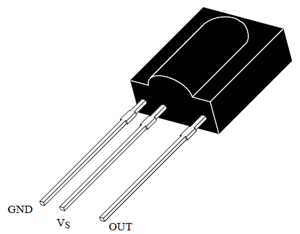
Hardware wiring is very simple. It needs just 3 wiring :

1.Connect TX to Arduino digital pin 9
2.Connect RX to Arduino Digital pin 10
3.Connect GND to Arduino's GND

And don't forget to insert sim into GSM modem


Note :- 

   
Upload code into arduino then connect the GSM modem otherwise you may encounter error like "Error"  .

Execution :-

Before execution make sure the hardware connection and coding part is done correctly


1.In arduino ,Open the Serial monitor (Ctrl +Shift + M) or tools -->Serial Monitor

2. Now Type and enter 's' for sending text (Check the Image)

The text that we entered in program has not been displayed but the full text will be sent no worries


Now check your mobile, you would have received an sms


3 To receive Sms from someone , just open serial monitor again and Type 'r' . This will show the sms and the number of the sim (Check the Image)


Yup i succeeded doing it . check My SS(ScreenShot) last image


Check and Arduino's serial monitor and Screenshot


 If you face any issues, you can contact me.I can help you online .

Regards,
lkkarthikeya@gmail.com


#SMS
#Send
#Receive
#DIY
#Wireless
#Arduino
#project
#Code


22 February 2016

Arduino based EarthQuake detector with coding DIY


Before going into this project i would like to tell you that this is just a school project . Ofcourse I did this during my third year of college and this project may help the Beginners who wants to learn Arduino.

Description
     Here i have used 3-axis Accelerometer Sensor interfaced with Arduino . whenever the Accelerometer is shaken or mover there will be a buzzer sound beeping and i call it a EarthQuake Detector

Components/Software required

1. Arduino UNO
2. Accelerometer Sensor (ADXL3xx)
3. BreadBoard
4. Jumper Wires (Female to male) -6
5. Buzzer / LED (For indication)
6. Arduino IDE Software - https://www.arduino.cc/en/Main/Software


Accelerometer Sensor (ADXL3xx)

Arduino Uno

                                                   
Connections

1. ST - A0
2. Z - A1
3. Y - A2
4. Z - A3
5. GND - A4
6. VDD - A5
7.Buzzer or LED on Digital PIN 12 and Digital Ground the -ve terminal of Buzzer/LED

You could use male to female jumper wires to connect accelerometer to Arduino Analog Pins


Coding :

1.First we have to find the values of accelerometer in its actual position then write actual code for the buzzer indications


TEST CODE :

Before Uploading the sketch make sure you have given the Hardware connection correctly and place Accelerometer in a narrow surface.

Here is the test code Copy paste in Arduino IDE


const int xpin = A3;                  // x-axis of the accelerometer
const int ypin = A2;                  // y-axis
const int zpin = A1;                  // z-axis (only on 3-axis models)

void setup()
{
  // initialize the serial communications:
  Serial.begin(9600);

}

void loop()
{
  // print the sensor values:
  Serial.print(analogRead(xpin));
  // print a tab between values:
  Serial.print("\t");
  Serial.print(analogRead(ypin));
  // print a tab between values:
  Serial.print("\t");
  Serial.print(analogRead(zpin));
  Serial.println();
  // delay before next reading:
  delay(500);
}


2.Now compile the code  .

3.Connect the Arduino to PC and Upload the code . If you get any error regarding ports  then go to
   Tools--> Ports and change the port . This will work .

4 . Open Serial monitor . Tools --> Serial Monitor . Now you will be seeing X,Y,Z values of Accelerometer in its surface position . When you move the Accelerometer the value will be changed

5. Note the optimu value . I got 300   280   300 . If you get a different value note it and change in the Following code

Now lets check the final code...


Final Code:

Note: If you get any other value than 300   280   300 , make change in code at xmin,ymin and                zmin


int buzzerop = 12;
int xpin = A3;                   // x-axis of the accelerometer
int ypin = A2;                   // y-axis
int zpin = A1;
long xmin=300;   //     If you get different value while running the TEST.ino code
long ymin=280;   //     Put that here
long zmin=300;   //      300    280    300 are the value taken from my TEST.ino output
long x=0;
long y=0;
long z=0;

void setup()
{
  Serial.begin(9600);

  pinMode(12,OUTPUT);

}

void loop()
{
   x = analogRead(xpin);
   y = analogRead(ypin);
   z = analogRead(zpin);

 
   if(y<ymin || x<xmin || z<zmin)               // the buzzer will be beeped only if they cross this condition
   {
     digitalWrite(12,HIGH);
     delay(500);
   }
   else
   {
     digitalWrite(12,LOW);
          delay(250);
   }
}


Thats all folks , whenever you shake or tilt the Accelerometer there will be a Buzzer sound.

If you want the Device to be more sensitive then alter the values of  X , Y , Z


If you cannot get the output contact me :-

lkkarthikeya@gmail.com


#DIY
#Arduino
#Project
#Earthquake
#detector
#Accelerometer